Indicators on Wedge Barriers You Need To Know
Table of ContentsFascination About Wedge BarriersThe Only Guide for Wedge Barriers

18 may be done faster, quickly, and cost effectively. FIG. In particular embodiments, the anchor 30 may be a steel framework including plates, beams(e. g., I-beams ), and/or various other structures that are protected within the structure 14, which may be concrete. At the surface area 12, an upper side 28 of the support 30 may be at the very least partly revealed
, thereby enabling the accessory of the obstacle 10 to the support 30. g., threaded holes)in one or more light beams or plates of the anchor 30 may be subjected to the surface 12. In this way, screws 32 or other mechanical fasteners may be utilized to secure the obstacle 10 to the support 30. As the obstacle 10 is installed to the surface 12 of the foundation 14, collection of debris and other product under the obstacle may be lowered, and parts of the bather 10 might not be revealed to listed below quality environments. As indicated by reference numeral 52, the lifting device 50 includes elements disposed under the wedge plate 16. The parts 52 under the wedge plate 16 might consist of an electromechanical actuator, a webcam, one or more cam surface areas, and so forth. In addition, the training mechanism 50 includes a spring setting up 54
The spring pole 58 is coupled to a cam(e. g., webcam 80 received FIG. 4) of the lifting mechanism 50. The springs 60 disposed concerning the springtime pole 58 are kept in compression by spring sustains 62, consisting of a taken care of springtime assistance 64. That is, the set spring support 64 is dealt with relative to the foundation 14 and the remainder of the bather 10.
See This Report on Wedge Barriers
The continuing to be pressure applied to
the cam web cam deploy the wedge plate 16 may might provided offered an electromechanical actuator 84 or other actuator. The spring assembly 54 and the actuator 84(e. Wedge Barriers. g., electromechanical actuator)might operate together to equate the cam and raise the wedge plate 16.
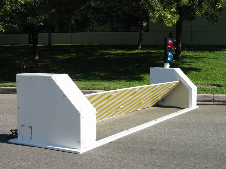
As discussed above, the spring assembly 54 exerts a consistent pressure on the camera, while the electromechanical actuator may be regulated to apply a variable pressure on the camera, thus making it possible for the lifting and reducing( i. e., releasing and withdrawing )of the wedge plate 16. In specific embodiments, the continuous pressure used by the spring assembly 54 may be adjustable. g., electromechanical actuator) is handicapped. As will be appreciated, check out here the spring setting up 54 might be covered and secured from debris or other elements by a cover plate(e. g., cover plate 68 displayed in FIG. 4) that may be substantially flush with the raised surface 38 of the structure 14. As mentioned above, in the deployed setting, the wedge plate 16 offers to obstruct gain access to or travel beyond the obstacle 10. For example, the obstacle 10(e. g., the wedge plate 16 )might obstruct pedestrians or cars from accessing a residential or commercial property or pathway. As discussed above, the barrier 10 is connected to the support 30 safeguarded within the foundation 14,
front braces 71. As an outcome, the link assemblies 72 may pivot and turn to make it possible for the collapse and extension of the link settings up 72 during retraction and deployment of the bather 10. The affiliation settings up 72 reason movement of the wedge plate 16 to be limited. For example, if an automobile is taking a trip in the direction of the released wedge plate 16(e. As an example, in one circumstance, the safety legs 86 might be prolonged duringupkeep of the barrier 10. When the safety this legs 86 are deployed, the safety legs 86 sustain the weight of the wedge plate 16 against the surface 12. Therefore, the lifting mechanism 50 might be deactivated, serviced, gotten rid of, replaced, etc. FIG. 5 is partial perspective sight of an embodiment of the surface-mounted wedge-style barrier 10, highlighting the cam 80 and the webcam surfaces 82 of the training device 50. Specifically, 2 camera surface areas 82, which are described as lower webcam surface areas 83, are positioned listed below the webcam 80. The reduced cam surfaces 83 may be taken care of to the surface area 12 (e. As an example, the lower camera surface areas 83 and the placing plate 85 might form a single item that is protected to the support 30 by screws or other mechanical bolts. Furthermore, 2 cam surfaces 82, which are described as top cam surface areas 87, are placed over the camera 80 and coupled to (e. In various other personifications, interfering layers or plates may be placed in between the surface 12 and the lower cam surface areas 83 and/or the wedge plate 16 and the top cam surfaces 87 As pointed out over, the web cam
80 converts along the camera surface areas 82 when the wedge plate 16 is raised from the retracted setting to the deployed position. Additionally, as mentioned over, the spring assembly 54 (see FIG. 3 )might provide a force acting upon the web cam check out this site 80 in the instructions 102 via spring pole 58, which might reduce the force the electromechanical actuator 84 is called for to use to the camera 80 in order to activate and lift the wedge plate 16. 1 )to the released placement(see FIG. 4). As shown, the cam 80 consists of track wheels 104(e. g., rollers), which get in touch with and translate along the web cam surface areas 82 during procedure.